DX11 Pipeline
Graphics Pipeline
Shader Model 5 introduces several new stages into the graphics and programmable pipeline, as seen in the diagram below.

Input Assembler stage
This stage is responsible for preparing geometry input to be available for Vertex Shader.
First geometry needs to provide layouts, which indicates how vertices are arranged into memory (format,size,semantic).
Then we create an Input Layout to match Vertex Shader Input and Geometry input. Input Assembler will then fetch data accordingly to send it to vertex shader.
Vertex Shader
As in previous DirectX versions, Vertex Shader allows to modify vertices.
Please note two things:
- Since we have more shader stages, it's not always desirable to tranform them into projective space right away.
- In case of instanced drawing, vertex shader will be called Vertices Count * Instances Count times
Hull Shader
This stage is the first part for tessellation.
We receive data from Vertex Shader as control points (Patches), that we can modify in the hull shader.
Also we need to provide a Hull Shader Constant function which will provide tessellation factors (how much we tessellate input geometry).
Tessellation
This stage is not programmable, the graphics card tesselator will subdivide geometry according to control points and tessellation factors.
Domain Shader
This is when we finally process tessellated data.
Depending on the type of tessellation we asked for, we receive different type of data, but all in the form of barycentric coordinates.
We can then process every new generate vertex the way we want (displacement for example)
Geometry Shader
Geometry shader allows to completely modify geometry.
Instead of receiving vertices like in other stages here we receive a fully assembled primitive (line/triangle point), and from there we can any of those types (only one of those types, but we can generate several or none of those).
Stream Output
This stage is optional and can happen either after Vertex/Domain or Geometry stage.
Stream Output allows to directly output the modified vertices/primitives into a new Buffer, which can be reused later (it's a bit like render to geometry)
Rasterizer
This is controlled trough rasterizer state. Rasterization takes the primitives and prepare them for pixel shader (culling, clipping, depth test).
Pixel Shader
This works the same way as before, we can process every pixel that makes it on the screen.
Please also note in Shader Model 5 we can also have pixel shaders able to write into buffers as well.
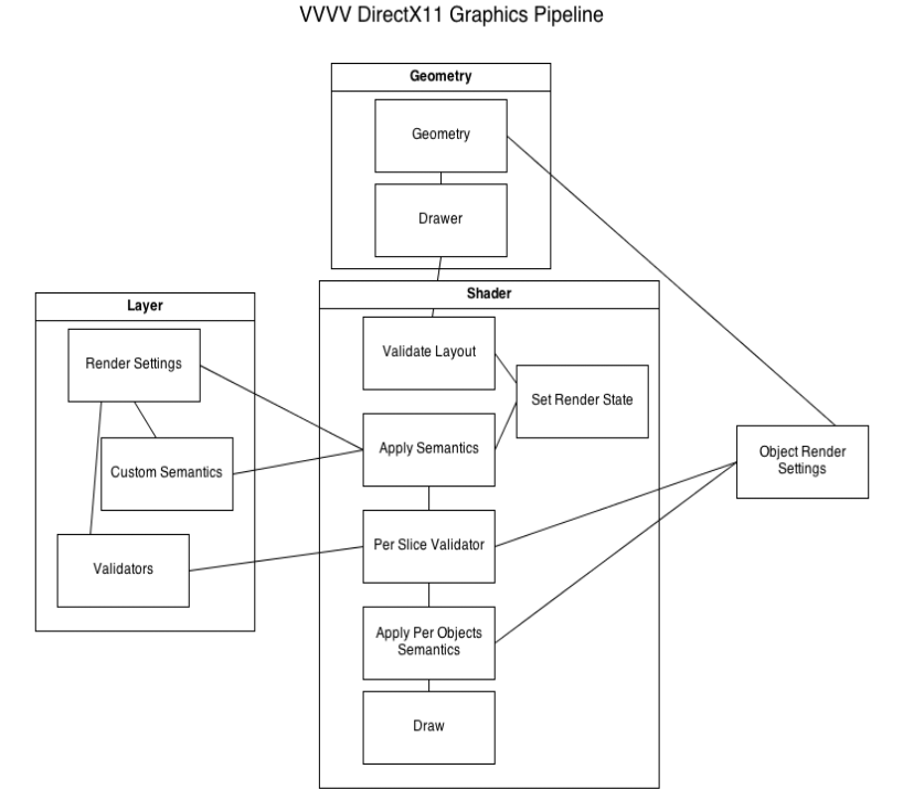
VVVV Pipeline
VVVV Pipeline has been adapted in some ways to works with new DirectX 11 features.

Geometry
Instead of having the DirectX9 Mesh, which doesn't exist anymore, it has been replaced by custom made and more flexible. Index buffers are not mandatory anymore and geometry topology can be any allowed by the pipeline (which means you can send point/line to a shader).
Additionally now we attach a Drawer to geometry. By default we attach a "default drawer", which will draw the object the same way it used to be in DirectX 9 version.
This drawer can be modified (this does NOT modify the geometry), to be able to use advanced features (Instancing, Indirect drawing, Per Vertex...)
Layer
Layer system has also be modified. Another page will provide more details about it, but to summarize.
- Layer provides only a render function, so it's not spreadable (as before)
- Now Renderer settings are provided to this render function, so you can access view/projection/render target size within render function.
- Layer can also be assigned validators, do for each slice we want to draw we can query validator if we want to render or not, this allows things like Frustrum Cull, GetSlice at layer level
- Besides the built in semantics (VIEW,PROJECTION), we can also assign our own (any type of data, including resources). This allows to pass the same data to shaders without having several pins to connect. Custom Semantic can also be mandatory, which means if the shader doesn't have semantic it will not run.
Shader node
Shader node works also in different way, and is processed as follows:
- Validate Layout: we check the geometry layout semantics and bind them to the vertexshader input from the selected Pass. Please note that DX11 will not accept missing semantics, so for example if your shader expects NORMAL and it's not provided by geometry the shader will NOT run (check the Layout Valid output pin to have details.
- Set Render State : We bind render states as in previous pipeline.
- Apply Semantics: We apply render semantics from Renderer and Layer (global semantics)
- Build object render settings: We build a small class which contains Current Geometry (with bounding box), and World transform
- Per Slice Validator : For each call, we sent render settings and object settings, Validators will decide if this slice needs to be drawn or not.
- Apply Per object semantics: Sets any semantic like WORLD, WORLDVIEW...
- Draw : Access the geometry draw and process the draw.
